Methods to Distinguish PCB and PCBA:How to produce PCBA based on PCB design drawings?Detailed Explanation of Precautions for Circuit Board Testing during PCBA Manufacturing In the circuit board testin
Methods to Distinguish PCB and PCBA:
1. Professional Testing Equipment
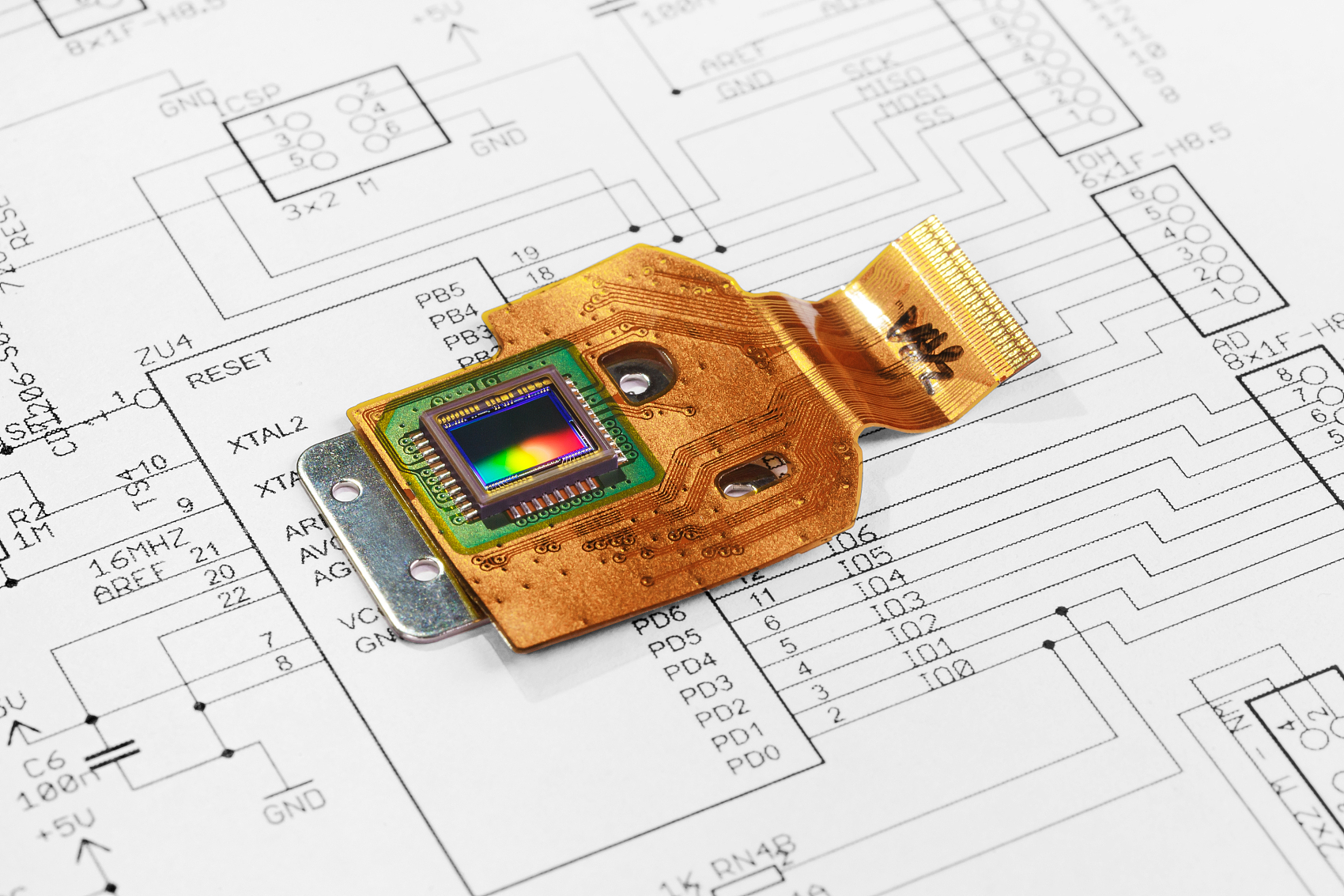
- The internal structure of PCB is relatively simple, only with circuits and substrates; while the installation of components can be clearly seen in PCBA.
2. Circuit Connectivity Test
- Conducting connectivity tests on PCB may only show the conduction of the lines; PCBA can reflect the connectivity and performance of the entire circuit including components.
3. Review Design Files
- By comparing the design diagram of PCB and the assembly diagram of PCBA, the PCB design diagram only contains the circuit layout, while the PCBA assembly diagram will show the layout and installation information of components.
4. Thermal Imaging Analysis
- Under working conditions, due to the heat generated by components in PCBA, the thermal imaging diagram will show temperature differences in different areas; PCB usually has a more uniform temperature distribution.
5. Chemical Analysis
- Conducting chemical analysis on the board, more types of metals and materials may be detected in PCBA, coming from various electronic components.
6. Observe Production Batches and Numbers
- The batch and number identifications during the production process may be different. PCBA may have more assembly-related identifications.
7. Ask Suppliers or Manufacturers
- Consult directly with the suppliers or manufacturers providing the products to obtain accurate information to determine whether it is PCB or PCBA.
How to produce PCBA based on PCB design drawings?
To produce PCBA based on PCB design drawings, the following steps can be followed:
1. Schematic Design: Use professional circuit design software to design the schematic diagram, ensuring that information such as circuit components, connections, and parameters is included.
2. PCB Design: Convert the schematic diagram into an actual circuit board design, involving adding components, adjusting positions, defining connection lines and routing rules, etc.
3. Generate Manufacturing Files: After completing the PCB design, convert it into manufacturing files, such as Gerber files, drilling files, patch files, and silk-screen files, etc.
4. Material Procurement and Preparation: According to the manufacturing files, purchase the required circuit boards, components, soldering materials, connectors, etc., and carry out the preparation work.
5. SMT Patch and DIP Plug-in Welding: Perform SMT patch and DIP plug-in welding of the circuit board to install the components on the circuit board.
6. Circuit Board Testing: Test the completed PCBA to ensure its electrical performance and functions are normal.
It should be noted that this is only a general process. The actual production process may vary depending on specific circumstances and requires professional equipment and technical support. If you have no relevant experience, it is recommended to seek the help of professional PCB manufacturers or electronic engineers.
Detailed Explanation of Precautions for Circuit Board Testing during PCBA Manufacturing
In the circuit board testing stage during PCBA manufacturing, the following are some matters that require special attention:
1. Stability of the Testing Environment
- Ensure the stability of the temperature, humidity, and power supply in the testing environment to avoid interference from environmental factors on the test results.
- Keep the testing site clean to prevent dust and other impurities from affecting the testing equipment and PCBA.
2. Calibration and Maintenance of Testing Equipment
- Regularly calibrate the testing equipment to ensure the accuracy and reliability of the test data.
- Conduct daily maintenance of the testing equipment, promptly detect and repair equipment failures to ensure its normal operation.
3. Accuracy of the Testing Procedures and Standards
- Write detailed and accurate testing procedures, clearly define the testing steps, parameter ranges, and acceptance criteria.
- The testing standards should be consistent with the product design requirements and industry norms.
4. Training and Skills of Operators
- Testing operators should receive professional training to be familiar with the operation of the testing equipment and the testing process.
- Enhance the operators' ability to judge the test results to avoid misjudgment and missed judgment.
5. Electrostatic Protection
- During the testing process, adopt effective electrostatic protection measures to prevent damage to the sensitive components on the PCBA caused by static electricity.
6. Rationality of the Testing Sequence
- Plan a scientific testing sequence. Conduct simple appearance and connectivity tests first, followed by complex functional and performance tests.
- Prioritize tests for items that may affect subsequent tests.
7. Data Recording and Analysis
- Record the data and results during the testing process in detail, including the testing time, tester, test parameters, and test conclusions, etc.
- Analyze the test data to promptly discover potential quality issues and trends.
8. Standardization of Fault Handling
- When faults are detected during testing, perform fault diagnosis and repair in accordance with the standardized process.
- Re-test the repaired PCBA to ensure its performance meets the requirements.
9. Representativeness of Sample Extraction
- If it is a sampling test, ensure that the extracted samples are representative and can reflect the quality status of the entire batch of PCBA.
10. Consistency with Design Files
- During the testing process, always refer to the PCB design files and schematics to ensure the completeness and accuracy of the test items.
11. Safety Protection
- Pay attention to electrical safety during the testing process to avoid accidents such as electric shock.
12. Compatibility Testing
- If the PCBA is to be used in conjunction with other components or systems, conduct compatibility tests to ensure it can operate normally in the actual application environment.
If a PCBA fault is found during the testing process, how should it be located and solved?
If a PCBA fault is found during the testing process, how should it be located and solved? The following steps can be followed to locate and solve the problem:
1. Observe the fault phenomenon
- Carefully record the fault manifestations, such as whether it is completely non-functional, abnormal output, failure of specific functions, etc.
2. Refer to the test data
- Review the data collected during the test, such as voltage, current, resistance value, etc., to determine if there are parameters that exceed the normal range.
3. Use tools for detection
- Use tools such as multimeters, oscilloscopes, and logic analyzers to measure and analyze the relevant circuits.
- Check whether the power supply lines are normal and whether the voltage at each node meets the design requirements.
4. Analyze the schematic and PCB layout
- Compare with the schematic diagram to determine the possible location of the fault and related components.
- Check the PCB layout to check for short circuits, open circuits or unreasonable wiring.
5. Component detection
- Conduct individual tests on suspected faulty components to check whether they are damaged, have degraded performance or are installed incorrectly.
- The substitution method can be used to replace the suspected faulty component with a known good component to determine if it is a component problem.
6. Check the solder joints
- Use a magnifying glass to check whether there are problems such as virtual soldering, short circuits, and cold soldering at the solder joints.
7. Software troubleshooting (if applicable)
- For PCBA with program control, check whether there are errors in the software settings and code logic.
8. Module-by-module troubleshooting
- If the PCBA function is complex, it can be divided into different modules for individual testing to gradually narrow down the fault range.
9. Consult professionals or technical support
- If you cannot locate the fault yourself, you can seek help from more experienced colleagues, engineers or the manufacturer's technical support.
10. Solve the fault
- Once the fault point is determined, take corresponding solutions, such as re-soldering, replacing components, modifying the wiring or repairing software problems.
11. Re-test
- After the fault is solved, conduct a comprehensive re-test on the PCBA to ensure that the problem has been completely solved and that other functions are not affected.
Share some practical cases of successful prevention of PCBA faults:
Case One:
In the PCBA design of a certain consumer electronic device, in order to prevent faults in the power supply part, the designer selected high-quality power management chips during component selection and equipped them with filter capacitors and inductors of sufficient capacity. In the PCB layout, the power-related components were centralized, and wide power lines and ground lines were adopted to reduce the impedance of the power lines. At the same time, overvoltage protection and overcurrent protection circuits were added to the circuit. After long-term use and various environmental tests, no faults occurred in the power supply part of this device.
Case Two:
The PCBA of an industrial control device faced a complex electromagnetic environment. During the design, a multilayer PCB was adopted, in which a ground layer and a power layer were specially set to enhance the electromagnetic shielding effect. For sensitive signal lines, a differential routing method was adopted, and magnetic beads and capacitors were added at key positions for filtering. In addition, the enclosure was made of metal material and was well grounded, effectively preventing the influence of external electromagnetic interference. This device operated stably in an industrial site with strong electromagnetic interference, and no faults caused by electromagnetic interference occurred.
Case Three:
In the design of a car electronic PCBA, considering the vibration and temperature changes during the operation of the car, components with high vibration resistance and a wide temperature operating range were selected. On the PCB, reinforcement points and buffer materials were added to reduce the impact of vibration on solder joints. At the same time, the component layout was optimized through thermal simulation analysis to ensure good heat dissipation. During the long-term use of the car, this PCBA withstood the tests of various harsh conditions and no faults occurred.
Case Four:
The PCBA of a certain medical device had extremely high reliability requirements. During the design process, the redundant design method was adopted. For the key signal processing circuits, backup components and circuits were added. At the same time, strict reliability tests were conducted, including high-temperature aging tests and humidity tests. Eventually, this device operated stably for a long time in the medical environment, ensuring the smooth progress of medical work.
These cases demonstrate that by taking effective preventive measures in the design stage, the reliability and stability of PCBA can be significantly improved, and the occurrence of faults can be reduced.
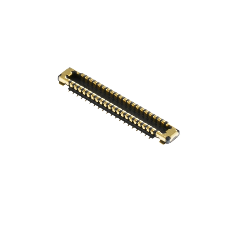
 LCN (LCN Electronics)Board-to-